A Practical Guide to Mechanical Joining Tool Selection and Best Practices
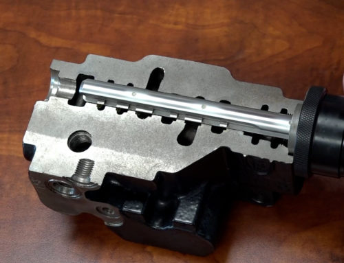
Mechanical joining is the process of joining a tube to a fixed container, like a flange or fitting. Widely used in applications such as hydraulic fittings, transmission blocks, and fluid lines, it offers a cost-effective alternative to welding or brazing. Successful joining hinges on selecting the appropriate tool, which can be done using the following guide.

Selecting The Right Tool
When choosing a mechanical joining tool, there are several factors that need to be considered:
Tube OD (Outer Diameter) & Wall Thickness
Tube specifications are required to select the right size tool but can also influence the number of rolls required and the amount of expansion needed to achieve complete groove fill.
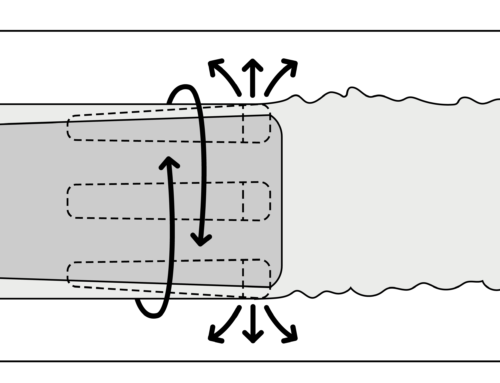
Length of Expansion
The portion being expanded defines the working area of the tool.
Target Size or Wall Reduction
Specifies the desired outcome of the joining process and influences the geometry of the tool.
Space Constraints
Describes any limitations in accessing the part. This is common when expanding something inside of another part, like a drain tube in a motor, requiring special reach.
Bends in the Tube
If a bend needs to be accommodated, the distance from the tube end to the bend will need to be understood, as it limits the stroke of the mandrel.

Selecting The Right Rolling Method
The tube and application requirements will determine the final design of the tool, but the method of expansion will determine the process used.
Rolling To Size
In mechanical joining, rolling to a size is the most common method of expansion. This is when a tube is rolled to a target ID using some type of visual cue, like a piece of tape, or by setting a mandrel stop. As long as the parts adhere to the manufacturing tolerance, the process is easy and repeatable.
When starting a job, the below procedure is recommended to determine the right position of the mandrel stop:
- Determine a target size
- Expand the first tube in the series
- Measure the tube ID and compare to the target
- Adjust the mandrel stop as needed
- Expand the second tube
- Measure & check size
- Repeat until target size achieved
Since the expansion is controlled visually or with a stop, any style of drill or motor can be used.
Rolling To Torque
Torque controlled expansion uses an electronic or pneumatic method of monitoring torque, triggering the expansion to stop once a specific value is reached. The most precise method for monitoring torque is with an electric rolling motor and an electronic digital torque control. An electronic torque control works by monitoring the amperage (amp) draw of the motor and cutting the power to the motor once the requirement is reached.
Pneumatic motors can also be used when rolling to torque if equipped with a clutch mechanism. Increasing the torque adjustment increases the compression on the spring, allowing the motor to work to a higher torque. During expansion, torque will increase until it reaches the setting on the adjustment, tripping the motor and shutting off the air supply.
The same rolling procedure would be used in torque-controlled applications, with the modification being the adjustment made on the controller:
- Determine a target wall reduction
- Expand the first tube in the series
- Measure the tube ID and compare to the target
- Adjust the torque setting as needed
- Expand the second tube
- Measure & check size
- Repeat until target is achieved
Selecting the appropriate mechanical joining tool is critical for achieving strong, reliable, and consistent joints. By carefully considering tube specifications, and application constraints, you can ensure a successful joining process. Whether you choose to roll to a size or a torque, consistent measurement and adjustment are essential for achieving the desired results.
Contact our applications team to learn more about mechanical joining applications.